

模型孔中化学气相渗透过程的热解碳沉积模拟
[汤哲鹏1  , 张中伟
, 张中伟2 , 房金铭2 , 彭雨晴1 , 李爱军1 , 张丹3 ]
, 张中伟]
|
|


作者简介: 汤哲鹏(1987-), 男, 博士研究生. E-mail: tangzhepong@shu.edu.cn
研究耦合均气相反应机理和总括反应机理, 以模拟甲烷在模型孔中的热解碳沉积过程。在平推流反应器模型中, 利用均气相反应机理对甲烷裂解的气相组分的变化进行模拟, 并将平推流反应器相应位置的气体组分浓度作为模型孔入口初始浓度。运用包含总括反应机理及氢气抑制模型的热解碳沉积模型, 对甲烷在模型孔中的化学气相渗透过程进行模拟。在温度1373和1398 K, 甲烷压强10~20 kPa, 停留时间0.08和0.2 s下, 沿模型孔深度方向的热解碳平均沉积速率的模拟结果与文献报道的实验结果有较好的吻合。模拟结果表明: 热解碳平均沉积速率随甲烷压强和模型孔深度的增加而增大, 且通孔的沉积速率要低于相应实验条件下一端闭孔的模型孔沉积速率。
Coupling homogeneous gas-phase reaction mechanism with lumped reaction mechanism, the pyrocarbon deposition process of the methane pyrolysis was simulated within the capillaries. The initial concentrations for the involved gas-phase species at the mouth of capillary are obtained firstly by computation of the plug flow using homogeneous gas-phase reaction mechanism during methane pyrolysis. Chemical vapor infiltration of pyrocarbon from methane in the capillary is simulated by deposition model, hydrogen inhibition model and lumped reaction mechanism. Predicted results for the mean deposition rate along the capillary depth are well validated by previously published experimental results, in which, at temperatures of 1373 and 1398 K, methane pressures are ranging from 10 to 20 kPa, and residence times are of 0.08 and 0.2 s. Simulated results show that the gradient of the mean deposition rate profile increases with methane pressure and capillary depth, and the deposition rate for transition capillary is lower than the corresponding closed capillary.
在高温炉内, 烃类气体经化学气相渗透(CVI)过程, 在碳纤维预制体内生成作为碳碳(C/C)复合材料基体的热解碳[1, 2, 3]。很长一段时间以来, 为避免出现由扩散限制引起的表面结壳, 一般推荐在低温低压条件下制备C/C复合材料[4]。碳纤维预制体是包含有纤维束间大孔(100 ~1000 μ m)和纤维束内小孔(1~10 μ m)的多尺度孔隙结构编织成型构件。在CVI过程中, 小孔孔隙因比表面积大而优先致密, 而碳源气体很难扩散至大孔孔隙内部, 故易形成表面闭孔, 成为致密高密度C/C复合材料的瓶颈。
为分析热解碳在预制体内纤维束间大孔的沉积速率分布, Hü ettinger等[5]用1.0 mm模型孔简化预制体大孔的复杂结构。胡子君等[5, 6]首次报道了在温度1373 K、压强20 kPa (纯甲烷)和30 kPa(甲烷/氢气为7:1)下, 热解碳的沉积梯度沿模型孔深度方向逐渐升高的实验结果。为实现该过程, 必须保证甲烷在模型孔入口处几乎无分解, 即要求较高的气体流速[7]。因此, 热解碳在模型孔中的沉积实验对C/C复合材料的制备具有直接的指导意义。在此之前, 张伟刚等[4]模拟了当气体在模型孔外停留时间较小时, 通过增加甲烷压强和模型孔长度使得沿模型孔深度方向热解碳沉积速率梯度增加。但该模拟只适应于热解碳沉积初期, 并且设定孔内比表面积一直不变。本研究则模拟了在模型孔中甲烷裂解沉积热解碳的整个沉积周期, 其中包含模型孔内径演变, 即对应模型孔比表面积的持续变化。
本研究采取徐伟等[8]提出的包含1074个气相反应的均气相烃类裂解化学反应过程机理, 对热解碳在模型孔的沉积过程, 按文献报道方法[9, 10, 11, 12]数值模拟了热解碳致密碳毡整个CVI沉积过程, 并按文献报道方法[13, 14]采用氢气抑制模型修正CVI过程中相应的表面反应速率常数, 以耦合详细的均气相反应机理、总括反应机理、扩散-对流方程及自定义的模型孔方程, 为后续研制水平和垂直方向均匀致密C/C复合材料提供理论依据[15]。
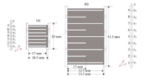
采用Hü ettinger课题组的模型孔长度为17 mm的“ 小反应器” 和模型孔长度为32.5 mm的“ 大反应器” (图1), 且采用其报道的工艺参数数据[5]。在竖直方向x轴上, 点xj表示编号为No.j模型孔的圆心坐标。在氧化铝陶瓷管和模具内核之间形成2 mm窄缝(图示两侧带箭头可流动空间), 且停留时间与窄缝部分长度相关。小反应器No.4模型孔和大反应器No.5模型孔相通, 用于与一端闭孔的模型孔作对照及验证气流在窄缝中的对称性。当分析甲烷压强影响时, 甲烷压强在10到20 kPa间变化, 温度分别为1398 K (小反应器)和1373 K(大反应器), 停留时间都为0.08 s。当分析气体停留时间的影响时, 各反应器的压强为20 kPa, 停留时间为小反应器0.08 s和大反应器0.2 s。
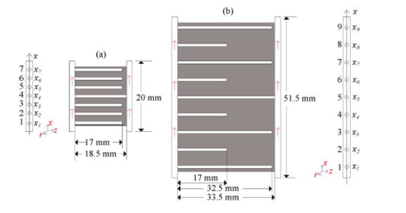 | 图1 含内径为1 mm的模型孔的基底示意图Fig. 1 Sketch of the substrates of capillaries with a diameter of 1.0 mm((a) Small reactor; (b) Large reactor No.4 of small reactor and No.5 of large reactor are transition capillaries) |
在甲烷裂解沉积热解碳的CVI过程中, 气相中形成了氢气, 各种轻质烃如甲烷及大组分烃如多环芳香烃(PAHs)等[16, 17]。在热解碳沉积过程中存在均气相反应和非均相表面反应的竞争关系。本研究通过平推流反应器模型和热解碳沉积模型来模拟在石墨模具内热解碳沉积过程, 并与实验数据比较作出验证。
由氧化铝管和模具内核组成的2 mm窄缝被看作平推流反应器。由于窄缝的间距很小且在窄缝中气流流速较高, 故认为在平推流反应器内各气相组分在横截面方向和轴向的扩散项较之对流项可忽略不计。由于模型孔外低的比表面积(约为1 mm-1)及气体相对短的停留时间, 气体在窄缝内的非均相反应可忽略。因此, 可单独用均气相反应机理来模拟甲烷在“ 平推流反应器(窄缝)” 的裂解过程。为模拟甲烷在模型孔中热解碳的沉积过程, 首先通过DETCHEMPLUG[18]模块计算获得在模型孔入口处气相组分浓度。所用详细均气相反应为徐伟等[8]提出的包含285个气相组分的1074个气相反应。
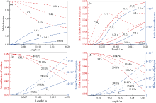
根据Hü ettinger等[5]给定的实验条件, 在不同压强和停留时间下, 本研究对甲烷在大、小反应器裂解的混合气体组分作了计算。当压强为20 kPa时, 对于小反应器, 不同停留时间下甲烷裂解得到的乙烯、乙炔和苯的组分含量变化如图2(a, b); 当停留时间为0.08 s时, 所计算的小反应器(图2(c))和大反应器(图2(d))在不同压强下甲烷和氢气的组分含量变化。将平推流反应器沿x轴方向对应各模型孔入口计算得到的气相组分浓度作为该模型孔入口处的初始气体组分浓度。
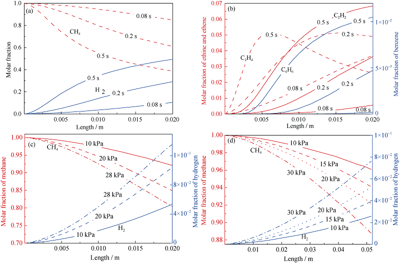 | 图2 甲烷裂解过程中计算得到的主要气相组分的变化曲线Fig. 2 Computed molar fraction profiles of major gas-phase species during the methane pyrolysis((a, b) 20 kPa, 1398 K and with various residence times in small reactor; (c) 0.08 s, 1398 K and with various pressures in small reactor; (d) 0.08 s, 1373 K and with various pressures in large reactor) |
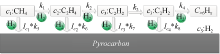
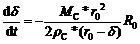
当计算得到上述给定实验条件下模型孔入口处的气相组分浓度后, 将对在模型孔中热解碳的化学气相沉积过程作单独模拟。由于采用详细反应机理较大的计算量和计算时间, 本研究用包含气相和表面相互作用的总括反应机理, 通过COMSOL模拟热解碳在模型孔中的沉积过程。该总括反应机理考虑了甲烷(c1)、乙烯(c2)、乙炔(c3)、苯(c4)和氢气(c5)五种组分浓度, 且用氢气抑制模型(抑制系数Ic1、Ic2、Ic3、Ic4)对表面反应的速率常数作了修改, 见图3。ki表示相应反应的速率常数, 以Arrhenius形式的反应动力学数据和氢气抑制函数来源于李爱军等[9], 其中Sv为模型孔的比表面积。根据图3甲烷裂解的平行连续反应模型, Ri(mol/m3s) (i=1, 2, 3, 4, 5)代表气相组分Ii在模型孔中的总生成速率的化学反应项, 见表1。且热解碳沉积的反应项R0:
 (1)
(1)
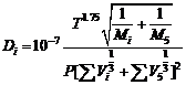
因在模型孔中没有气体流动, 即在模型孔中气体的对流质量传递模式可忽略, 因此, 在模型孔中只有扩散质量传递模式。由于模型孔的内径远大于分子的平均自由程, 故可忽略努森扩散。通过Fuller-Gidding经验公式可计算得到组分i的扩散系数Di(m2/s)(i=1, 2, 3, 4, 5), 其中氢气为稀释气体。
 (2)
(2)
T为卡尔文温度, P(Pa)为压强, Vi和V5分别为组分i和氢气的扩散体积。Mi和M5为组分i和氢气的摩尔质量。相应的原子和分子体积增量见表2。
当提供了上述参数和表达式, 热解碳在模型孔内沉积的质量守恒方程为:
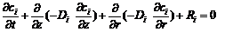 (3)
(3)
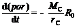
根据描述碳毡内孔隙率por变化的常微分方程[11]可导出在模型孔中孔隙体积分数的常微分方程:
 (4)
(4)
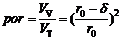
其中MC (1.2× 10⁻² kg/mol)和ρ C (1.95 g/cm3)分别是碳的摩尔质量和热解碳密度。比表面积Sv与模型孔的孔隙内径呈反比。在模型孔中热解碳的厚度“ δ ” 与“ por” 和“ Sv” 的函数关系如下:
 (5)
(5)
 (6)
(6)
其中VV为未被热解碳填充的模型孔中的体积, VT为模型孔的初始的未填充体积。将式(5)和式(6)代入式(4), 得热解碳沉积厚度的自定义模型孔方程:
 (7)
(7)
除了用于描述在模型孔中热解碳沉积的式(3)和式(7), 将通过平推流模型计算的对应位置的相关组分浓度作为模型孔入口边界条件:
对于小反应器:
r = 0, z = 0: ci = ci(xj) (8)
其中i = 1, 2, 3, 4, 5及j= 1, 2, 3, 5, 6, 7
对于大反应器:
r = 0, z = 0: ci = ci(xj) (9)
其中i = 1, 2, 3, 4, 5及j = 1, 2, 3, 4, 6, 7, 8, 9
对于小反应器中编号No.4模型孔和大反应器编号No.5模型孔为通孔, 故对模型孔两端都设置边界条件。最后, 在模型孔域内热解碳沉积厚度的初始条件为:
 (10)
(10)
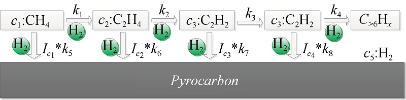 | 图3 由甲烷热解碳沉积的气相与表面反应相互作用原理图Fig. 3 Scheme of interaction between gas phase and surface for pyrocarbon deposition from methane |
| 表1 相关组分的反应项 Table 1 Reaction terms of related species |
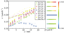
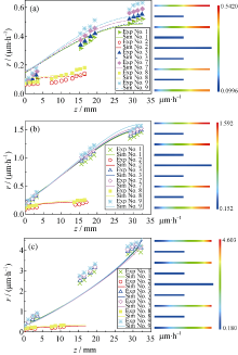
由图2(c)可知, 在小反应器内沉积热解碳的实验温度为1398 K, 停留时间为0.08 s时, 只有约7.5%的甲烷在平推流反应器出口处分解, 故在所有模型孔入口处气体组分浓度大致相同。经401 h (10 kPa)(图4)和184 h (20 kPa) (图5)沉积, 在模型孔入口处的预测结果较之实验结果偏高, 而在模型孔末端的预测结果得到了很好的再现。通孔No.4的沉积速率要低于其它模型孔, 通过模拟得到了很好的再现。因为气相前驱体的初始浓度在模型孔两端口都设定了, 较其它一端封闭的模型孔, 气相组分的扩散距离减少, 从而导致在模型孔中存在过多未成熟的气相组分, 而这些组分的沉积速率都很小[19]。图4右侧的云图展示了在整个基底的热解碳平均沉积速率分布, 最大和最小平均沉积速率是0.256 μ m/h和0.1380 μ m/h。在甲烷压强20 kPa下, 虽然对于模型孔编号No.1和No.2的模拟结果较之实验结果仍存在数值偏差, 但其他模型孔的模拟结果都比较理想。模拟结果的偏差可能与相关反应的动力学数据不准确有关, 这正说明在模型孔中使用详细反应机理的必要性[20]。图5右侧的分布云图显示最大和最小沉积速率分别为1.521 μ m/h和0.3670 μ m/h。比较图4和图5, 可知增大甲烷压强, 热解碳的沉积速率梯度得到了提高[21]。
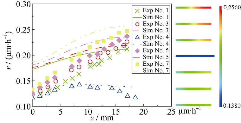 | 图4 小反应器中反应条件为1398 K、0.08 s、10 kPa时, 沿模型孔方向热解碳的平均沉积速率的实验结果与模拟结果的比较, 及相应的沉积速率云图(右)Fig. 4 Comparison of the computational predictions with the experimental data of the mean deposition rates as a function of the capillary depth in small reactor under the reaction conditions of 1398 K, 0.08 s, 10 kPa, and the cloud chart (right) of the related deposition rate for the substrate No.4 is a transition capillary |
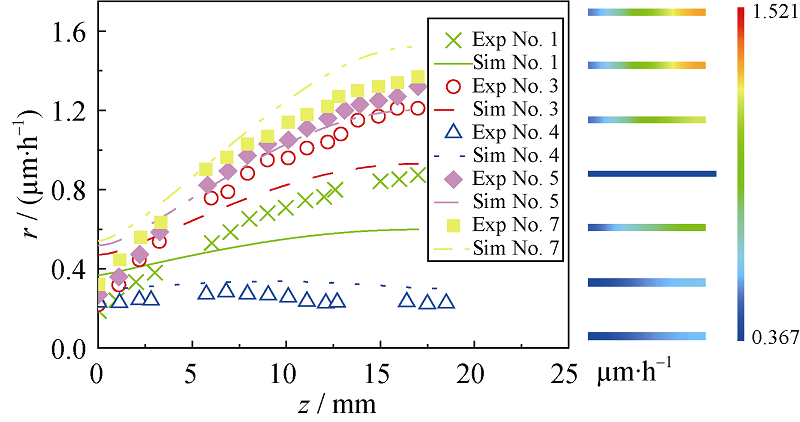 | 图5 小反应器中反应条件为1398 K、0.08 s、20 kPa时, 沿模型孔方向热解碳的平均沉积速率实验结果与模拟结果的比较, 及模型孔中相应的沉积速率云图(右)Fig. 5 Comparison of the computational predictions with the experimental data of the mean deposition rates as a function of the capillary depth in small reactor under the reaction conditions of 1398 K; 0.08 s; 20 kPa, and the cloud chart (right) of the related deposition rate for the substrate No.4 is a transition capillary |
在大反应器内实验条件为: 温度1373 K、停留时间0.08 s、甲烷压强分别为10、15和20 kPa时, 分别作150 h(10 kPa)、80 h(15 kPa)和50 h(20 kPa)的沉积实验。根据图6(a~c)所示模拟结果和实验结果除压强20 kPa外, 其他条件下实验结果通过模拟得到了很好的再现。从图2(d)看, 压强20 kPa、停留时间0.08 s的甲烷气流, 只有约8%的甲烷分解, 故各模型孔入口处平均热解碳沉积速率都相近。长度32.5 mm模型孔的平均热解碳沉积速率要高于长度17 mm模型孔。与长度17 mm模型孔比较, 长度32.5 mm模型孔使得甲烷裂解的反应序列延长生成更大的气相组分, 因此, 长模型孔内沉积速率有所升高。对比上文对小反应器的分析, 通孔No.5的平均热解碳沉积速率要低于其它模型孔。图6(c)所示最大热解碳沉积速率为4.603 μ m/h及最小热解碳沉积速率为0.180 μ m/h。平均热解碳沉积速率分布云图见图6右侧。根据上述分析, 在制备致密C/C复合材料的过程中, 热解碳的沉积速率受前驱体压强、反应器尺寸、预制体尺寸和预制体一边是否受阻挡的影响。
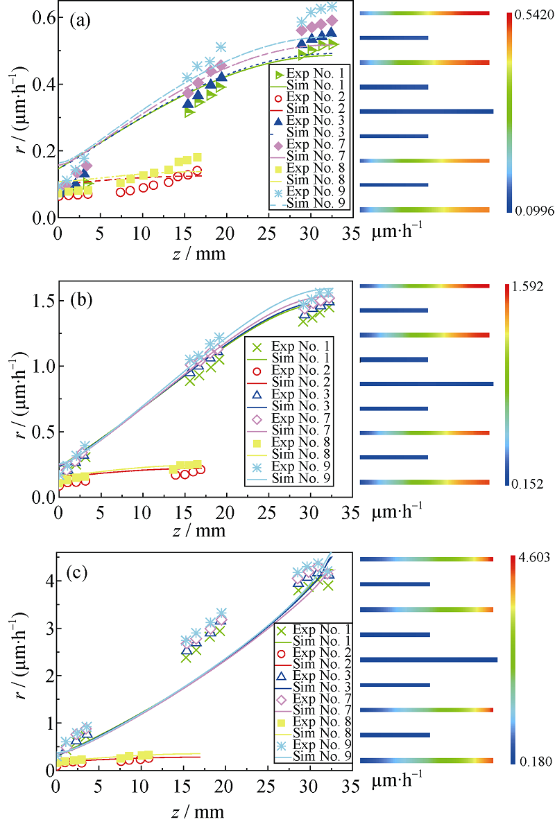 | 图 6 大反应器中反应条件为1373 K和0.08 s、压强分别为10 kPa(a)、15 kPa(b)、20 kPa(c)时, 沿模型孔方向热解碳的平均沉积速率实验结果与模拟结果的比较, 及模型孔中相应的沉积速率云图(右) Fig. 6 Comparison of the computational predictions with the experimental data of the mean deposition rates as a function of the capillary depth in large reactor under the reaction conditions of 1398 K, 0.08 s and 10 kPa (a), 15 kPa (b) or 20 kPa (c), and the cloud chart (right) of the related deposition rate for the substrate No.5 is a transition capillary Fig. 6 Comparison of the computational predictions with the experimental data of the mean deposition rates as a function of the capillary depth in large reactor under the reaction conditions of 1398 K, 0.08 s and 10 kPa (a), 15 kPa (b) or 20 kPa (c), and the cloud chart (right) of the related deposition rate for the substrate No.5 is a transition capillary |
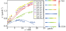
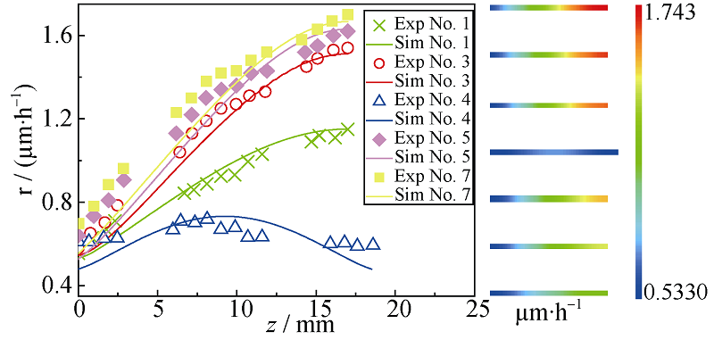
从图2(a)看, 在平推流反应器出口处甲烷有接近40%裂解, 且有30%摩尔分数的氢气产生。而当反应条件为温度1398 K、压强20 kPa和停留时间0.2 s时, 模型孔中经120 h沉积的平均热解碳沉积速率的模拟结果(图7), 相比停留时间0.08 s的模拟结果(图5), 与实验结果更吻合。在大反应器中, 对温度1373 K、压强20 kPa和停留时间0.2 s的甲烷裂解过程的模拟结果与实验结果相比(图8)的准确程度, 与图6(c)显示的模拟结果较之实验结果准确程度, 虽有一些差异, 但沿模型孔入口到末端的平均热解碳沉积速率变化趋势得到了很好重现。较之模型孔长度为32.5 mm的模拟结果, 模型孔长度为17 mm的模拟结果更好些。这表明该总括反应机理对于小反应器的模拟结果要好于大反应器, 对模拟结果的偏差可通过详细化反应机理解决。Marquaire等[22]和李爱军等[23]报道了以丙烷为前驱体, 热解碳沉积的详细非均相反应机理, 可适用于更广泛的实验条件。运用该详细反应机理[23], 可解决因反应条件和反应器条件变化而引起的偏差。根据大反应器和小反应器得到的模拟和实验结果, 可知停留时间由0.08 s变到0.2 s时, 停留时间对热解碳沉积的影响相对较小[5, 6]。
 | 图 7 小反应器中反应条件为1398 K和0.2 s、20 kPa时, 沿模型孔方向热解碳的平均沉积速率实验结果与模拟结果的比较, 及模型孔中相应的沉积速率云图(右)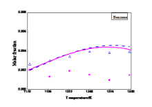 Comparison of the computational predictions with the experimental data of the mean deposition rates as a function of the capillary depth in small reactor under the reaction conditions of 1398 K, 0.2 s and 20 kPa, and the cloud chart (right) of the related deposition rate for the substrate No.4 is a transition capillary Comparison of the computational predictions with the experimental data of the mean deposition rates as a function of the capillary depth in small reactor under the reaction conditions of 1398 K, 0.2 s and 20 kPa, and the cloud chart (right) of the related deposition rate for the substrate No.4 is a transition capillary |
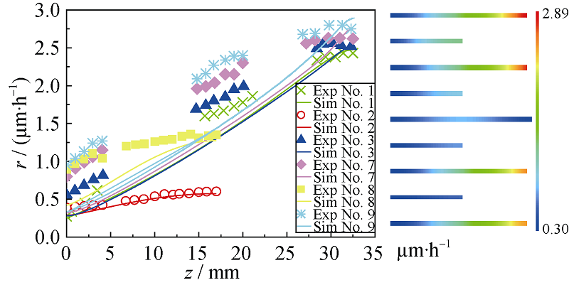 | 图 8 大反应器中反应条件为1373 K和0.2 s、20 kPa时, 沿模型孔方向热解碳的平均沉积速率实验结果与模拟结果的比较, 及模型孔中相应的沉积速率云图(右)Fig. 8 Comparison of the computational predictions with the experimental data of the mean deposition rates as a function of the capillary depth in large reactor under the reaction conditions of 1373 K, 0.2 s and 20 kPa, and the cloud chart (right) of the related deposition rate for the substrate No.5 is a transition capillary |
本研究通过耦合详细气相反应机理和总括反应机理, 并结合石墨模具中平推流反应器模型和含氢气抑制模型的热解碳沉积模型, 模拟了甲烷裂解的热解碳沉积过程。
选取的平均热解碳沉积速率的实验结果来自Hü ettinger等, 其中在大反应器和小反应器中包含不同甲烷压强和停留时间。通过实验结果和模拟结果的比较, 发现虽然模拟结果和实验结果间还有一定的差异, 但该物理-化学模型能很好地模拟热解碳在模型孔中的沉积过程。通过上述讨论, 在致密C/C复合材料过程中, 热解碳的沉积速率受气体压强、停留时间、反应器尺寸和碳纤维预制体的尺寸, 及碳纤维预制体一边是否阻挡有关。通过对在石墨模具的化学反应流模拟, 为采用烃类气体裂解制备C/C复合材料提供了沉积动力学基础。
The authors have declared that no competing interests exist.
| [1] |
|
| [2] |
|
| [3] |
|
| [4] |
|
| [5] |
|
| [6] |
|
| [7] |
|
| [8] |
|
| [9] |
|
| [10] |
|
| [11] |
|
| [12] |
|
| [13] |
|
| [14] |
|
| [15] |
|
| [16] |
|
| [17] |
|
| [18] |
|
| [19] |
|
| [20] |
|
| [21] |
|
| [22] |
|
| [23] |
|